This procedure neither replaces the calculation as defined in VDI 2230 nor meets the current state of technology. However, it will allow one to approximate a torque that does not cause a bolt fracture during assembly. The main reason for that the actual friction is lower than anticipated.
How to use reference values
Download full chapter: preload and tightening torques
Step 1: Friction coefficient μK = μG
In case of uncertainty about friction conditions in the threads and under the bearing surface, the lowest possible practical friction coefficient (e.g. initial assembly, maintenance, repair) μK = μG must be selected from table F.044.
Example:
Fasteners used are electro zinc plated Friction coefficient μK = μG = 0,14 – 0,24, lower friction coefficient μK = μG = 0,14
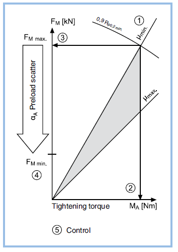
Step 2: Tightening torque MA max
Maximum permissible torque, 90 % utilisation of yield point (ReL) respectively the 0.2 % yield strength (Rp0.2) can be found in the tables from page F.048. The values assume that one uses either precision torque wrenches or precision power drivers with a tool inaccuracy of maximum 5 %.
Example:
Hex cap screw per ISO 4017, M12 property class 8.8, zinc plated. In Table on page F.049 look for M12 in the thread column, in the friction column look for μK = μG = 0,14. Now move over to the right half of the table under «maximum tightening torque under property class 8.8» you will find the Maximum tightening MA max. = 93 Nm
Step 3: Maximum Preload FM max
The maximum resulting preload MA max from that torque FM max can be found in the same tables.
Example:
In the left half of the table in column «property class 8.8» and on line «M12/0,14», the resulting maximum installation preload FM max = 41,9 kN
Step 4: Minimum preload FM min
The minimum preload can be calculated by dividing the maximum preload through the tightening factor αA – see table on page F.046.
Example:
For installations with commercial, modern torque wrenches, tightened in a uniform, uninterrupted fashion, with an estimated friction coefficient, a tightening factor αA = 1,6 to 2,0 must be applied. (see table at page F.046). For a signal type torque wrench, as used in the example, a tightening factor αA of 2,0 is adequate. We use a short screw M12x40, which only requires a small torque angle. This results in a relative stiff joint, therefore a lower tightening factor can be applied.
Assumed tightening factor αA = 1,8
Minimum expected preload (clamp load):
FM min = FM max/αA = 41,9 kN/1,8
FM min = 23,3 kN
Step 5: Double checking values,
checking using calculations in accordance with VDI 2230 is state of the art and is recommended for a safe design.
- Is the minimum preload FM min adequate for the intended application?
- Are surface pressures in the bearing areas brought in line with strength of clamped parts?
- How high is the residual clamp force when work forces are applied?
- Will the bolted joint be used in a manner not to exceed the fatigue limit?
If one applies a tightening torque MA that is lower than the stated torque value in the table, the resulting maximum preload FM will be lower as well. The minimum possible preload FM min would be
affected as explained in step 4. Users (engineers) ought to verify parameters to assure an adequate clamp load in the bolted joint.
Possible reason for the torque to be different:
- Friction is lower than anticipated, possibly leading to a bolt fracture during assembly
- Tightening tools are not as accurate as they should be, again leading to a premature bolt fracture either during assembly or in use.
- Clamped parts are deformed unexpectedly (head embeds into material)
- Inadequate knowledge of assembly personnel
Related Topics
|